BOX GUTTER WITH OUTLET AT ONE END, AND ACCEPTING VERTICAL FACES
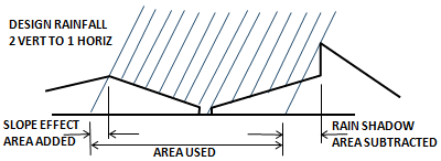
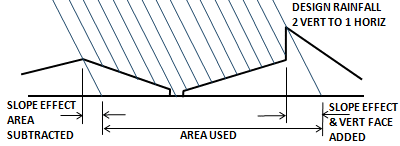
Allowing for rain shadow effects
Method of Calculating Catchment Areas due to rain shadow effects.
Rainfall calculated from all directions and worst case adopted.
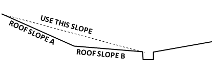
Roof Slopes for combined Roofs
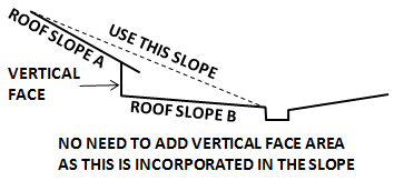
Note:
This free online box gutter calculator will size box gutters and rain water heads in accordance with the Australian Plumbing Code AS/NZS 3500.3 .2021 Part 3 Storm Water Drainage.
But can be used for anywhere in the world provided you know the rainfall intensity requirements for your local area. For areas using the International Plumbing code, or the Uniform Plumbing Code, as in the USA, the required intensity is for a storm recurrence interval of 100 years with duration of one hour.
The program can be used with or without adding vertical faces , or it can be used with a catchment on one side only, or any other combination. It doesn't matter which side is designated left hand side (LHS) or front and back.
The calculator is only suitable for draining to a rain water head at one end of the box gutter.
If draining to a sump with a side overflow, in the middle of the box gutter use this calculator.
If draining to a sump with a vertical overflow, in the middle of the box gutter use this calculator.
Trial Box Gutter Width
The minimum width allowed for commercial projects is 300mm, for domestic projects 200mm.
Experiment with this figure to get the depth of box gutter you require.
Box Gutter Slope
Slope should be from 1:40 to 1:200, however the calculator will give the depth of gutter required (if for some inexplicable reason) the gutter is laid without any slope. By the way, it is not a good idea to design a box gutter to be flat, as this allows ponding and rusting. But it is a good idea to allow for the fact that an unusual amount of box gutters end up flat.
Vertical faces
Enter the full vertical face area. The program does the 50% reduction in area as required by the Code.
Box Gutter Sizes
The depth shown is the minimum depth, which should occur at the upstream end.
The Down pipe diameter suggested
This is shown for reference purposes only. This is a size that will give approximataely the shallowest rain water head depth. Going smaller requires more head of water over the throat of the DP to push more water through. A larger down pipe will trigger Note 1 on figure H2 which requires the depth of the rain water head to be >= 1.25*DPdia.
For flows above 16L/s when the CSIRO formulas are used, this DP size equates to approximately 100mm water depth in the RWH.
Choose an available size (or any other size greater than 90mm dia.) and enter that for the calculation of the Rain Water Head. Smaller sizes result in a deeper RWH and larger sizes also result in a deeper RWH. (go figure? but hey that's the Code)
By the way the depth shown in the calculator allows for about 60mm freeboard.
Rain Water Heads
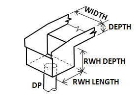
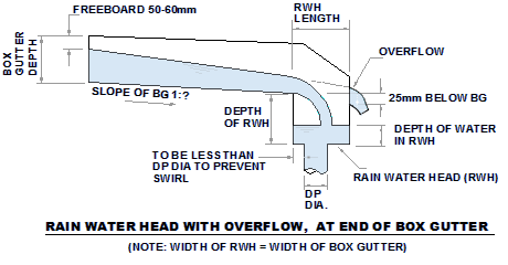
This is the rainwater head depicted in the code. As you can see it is a fail safe design. the overflow lip is
25mm below the base of the box gutter, and the overflow is the full width of the box gutter.
However, should you not like the look of this one, try Designing a Custom Rain Water Head.
More notes on overflowing and fail safe design
Important Note
The code only allows for flows up to 16 litres/sec total runoff in the Down pipe. It recommends that if this figure is exceeded, more downpipes should be added, or catchments reduced.
The graphs in the Code were confirmed by experimentation only up to a flow of 16 litres/sec, and for this reason the graphs do not go beyond this flow.
However these calculators are based on hydraulic formulas, with parameters adjusted to give results consistent with the Code. They work for all flows. Check out my Blog for comparison of different formulas.
Should you wish to go above the 16L/s barrier, this program reverts to formulas developed by the CSIRO many years ago.
This, hopefully will convince your certifier that the formulas are from a recognised Authority. This is now allowed under the National Construction Code. (NCC)
more info on this here How to go above 16L/s
However, bear in mind that if you use flows above 16 litres/sec you are beyond the scope of the Code.
Maximum allowable length
Unit Conversions
Rainfall calculated from all directions and worst case adopted.


Roof Slopes for combined Roofs


Note:
This free online box gutter calculator will size box gutters and rain water heads in accordance with the Australian Plumbing Code AS/NZS 3500.3 .2021 Part 3 Storm Water Drainage.
But can be used for anywhere in the world provided you know the rainfall intensity requirements for your local area. For areas using the International Plumbing code, or the Uniform Plumbing Code, as in the USA, the required intensity is for a storm recurrence interval of 100 years with duration of one hour.
The program can be used with or without adding vertical faces , or it can be used with a catchment on one side only, or any other combination. It doesn't matter which side is designated left hand side (LHS) or front and back.
The calculator is only suitable for draining to a rain water head at one end of the box gutter.
If draining to a sump with a side overflow, in the middle of the box gutter use this calculator.
If draining to a sump with a vertical overflow, in the middle of the box gutter use this calculator.
Trial Box Gutter Width
The minimum width allowed for commercial projects is 300mm, for domestic projects 200mm.
Experiment with this figure to get the depth of box gutter you require.
Box Gutter Slope
Slope should be from 1:40 to 1:200, however the calculator will give the depth of gutter required (if for some inexplicable reason) the gutter is laid without any slope. By the way, it is not a good idea to design a box gutter to be flat, as this allows ponding and rusting. But it is a good idea to allow for the fact that an unusual amount of box gutters end up flat.
Vertical faces
Enter the full vertical face area. The program does the 50% reduction in area as required by the Code.
Box Gutter Sizes
The depth shown is the minimum depth, which should occur at the upstream end.
The Down pipe diameter suggested
This is shown for reference purposes only. This is a size that will give approximataely the shallowest rain water head depth. Going smaller requires more head of water over the throat of the DP to push more water through. A larger down pipe will trigger Note 1 on figure H2 which requires the depth of the rain water head to be >= 1.25*DPdia.
For flows above 16L/s when the CSIRO formulas are used, this DP size equates to approximately 100mm water depth in the RWH.
Choose an available size (or any other size greater than 90mm dia.) and enter that for the calculation of the Rain Water Head. Smaller sizes result in a deeper RWH and larger sizes also result in a deeper RWH. (go figure? but hey that's the Code)
By the way the depth shown in the calculator allows for about 60mm freeboard.
Rain Water Heads


However, should you not like the look of this one, try Designing a Custom Rain Water Head.
More notes on overflowing and fail safe design
Important Note
The code only allows for flows up to 16 litres/sec total runoff in the Down pipe. It recommends that if this figure is exceeded, more downpipes should be added, or catchments reduced.
The graphs in the Code were confirmed by experimentation only up to a flow of 16 litres/sec, and for this reason the graphs do not go beyond this flow.
However these calculators are based on hydraulic formulas, with parameters adjusted to give results consistent with the Code. They work for all flows. Check out my Blog for comparison of different formulas.
Should you wish to go above the 16L/s barrier, this program reverts to formulas developed by the CSIRO many years ago.
This, hopefully will convince your certifier that the formulas are from a recognised Authority. This is now allowed under the National Construction Code. (NCC)
more info on this here How to go above 16L/s
However, bear in mind that if you use flows above 16 litres/sec you are beyond the scope of the Code.
Maximum allowable length
| Material | Base Metal Thickness (mm) | Max Length (metres) | Minimum expansion space (mm) |
| Aluminum | 0.90 | 12 | 50 |
| Copper | 0.60 | 9 | 50 |
| Copper | 0.80 | 15 | 50 |
| Copper | 1.0 | 26 | 50 |
| Steel Colorbond Zincalume | 0.55 | 20 | 50 |
| Steel | 0.75 | 25 | 50 |
| Stainless Steel | 0.55 | 20 | 50 |
| PVC | - | 10 | 30 |
| Zinc | 0.80 | 10 | 50 |
Unit Conversions
| Unit Conversions (Rounded) | Degrees |
||
| mm | sq.metres | Litres/s | Percent |
| inch | sq. feet | cu.ft/s | 1 in ? |
Copyright Ken Sutherland 2024
If you find that the programs save you time or money, please feel free to share the happiness with me.